Table Of Content
It still describes the whole system but with emphasis on its main function and more sub-processes for easy digestion. A DFD can be divided into levels and layers, starting with level 0; thus, users can focus on describing a particular stage. An external entity, also known as terminators, sources, sinks, or actors, is an outside process where information enters or leaves the system. Click it and drag it to where you want to add a title to the diagram. Type the title, and if you’d like to, adjust the font and type size using the shortcut keys at the top of the screen.
DFD Diagram Notations
In a data flow diagram, these components are generally represented as arrows and connectors. There are a few rules to keep in mind when creating a data flow diagram that’ll help you make sure your visualization is clear, consistent-looking, and accurate. Amber has been a software developer and technical trainer since the early 2000s. In recent years, she has focused on teaching AI, machine learning, AWS and Power Apps, teaching students around the world. She also works to bridge the gap between developers, designers and businesspeople with her expertise in visual communication, user experience and business/professional skills. She holds certifications in machine learning, AWS, a variety of Microsoft technologies, and is a former Microsoft Certified Trainer.
Data Flow Diagrams Symbols
Use a template from our gallery to help you start work on your data flow diagram. You can use the rectangle with a vertical line as drawn above, or you can choose one of your own as long as you continue to use that symbol to represent data stores. Your business most likely has more than one process, but it’s best to diagram them one at a time.
A Beginner's Guide to Data Flow Diagrams
The diagramming software tools like the above ones provide pre-ready templates that save your time and efforts. Here is our level 1 data flow example – a decomposition of the Clothes Ordering System illustrated in the context DFD. As you saw above context DFD contains only one process and does not illustrate any data store. Drive alignment with your team by collaborating in the same space.
However, a Physical DFD shows how the system is actually implemented now, or how it will be. For example, in a Logical DFD, the processes would be business activities, while in a Physical DFD, the processes would be programs and manual procedures. Three other experts contributing to this rise in DFD methodology were Tom DeMarco, Chris Gane and Trish Sarson.
It can be used to streamline the everyday systems and workflow of a business. Data flow diagrams are split into two categories based on the flow that needs to be visualized. A data flow diagram can either be a logical data flow diagram or a physical data flow diagram.
In an age where data reigns, data-defined software development emerges as the future of application creation. It untethers development from the confines of code, streamlining processes, fostering innovation and enhancing adaptability. DDS promises a world where software creation becomes more intuitive, collaborative and responsive to ever-changing business needs.
Network data flow is key to SRAM choice - EE Times
Network data flow is key to SRAM choice.
Posted: Sat, 14 Dec 2019 05:24:45 GMT [source]
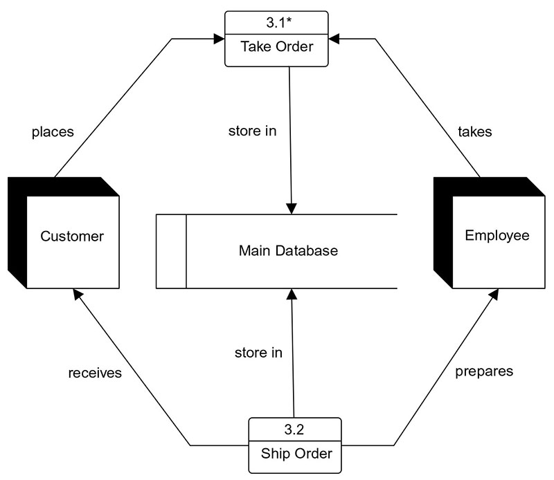
Data store
A process can perform several functions, from carrying out computations, categorizing information based on logic, or using business rules to change the flow. Click the highlighted text in the box and type the name of the external entity. For our example, we’re typing “customer.” You can use the curved arrow in the top left corner of the square to rotate the symbol. Delete a symbol by clicking it and pressing delete on your keyboard. In the left column of the screen, you’ll notice a lot of shapes and symbols.
A data flow diagram can help foster graphical communication between system designers and users. This can help engineers and developers understand the needs and wants of the user. Implementing a data flow diagram helps describe and demarcate the boundaries of a system. Without a data flow diagram, a company might struggle to understand where a system starts and ends.

This Level 2 DFD decomposes the “Place Order” process to contextualize the steps required to place an order — either by a customer or by a broker. Professionals in various industries, like software engineering, IT, ecommerce, and product management & design, can use DFDs to better understand, refine, or implement a new system or process. On a broader level, DFDs can help you streamline your business operations. When mapping out your processes, you‘ll gain insights into what does and doesn’t work. DFDs clarify the systems and processes necessary for your team to do their best work.
Visualize marketing campaigns and client and prospect info to take action, and track tasks and status updates for the team. Make sure you use our diagramming shapes library to represent each component with the right shape. Cisco offers data center and access networking solutions built for scale with industry-leading automation, programmability, and real-time visibility. Before getting to the steps, let’s go through some rules on making one first.
For this reason, it's important for a company to select a methodology and symbology and stay with it. As you embark on your journey into understanding what data flow is, remember that it is a dynamic and evolving field. Stay curious, keep exploring, and embrace the constant advancements in technology and data management.
This process of collecting and analyzing data helps them understand their readers' preferences and habits. Spotify uses data flow to analyze user listening habits and recommend new music. The company collects data on what songs users listen to, how often they listen to them, and when they listen to them.
When used through an entire development process, they first document the results of business analysis. Then, they refine the representation to show how information moves through, and is changed by, application flows. A logical data flow diagram focuses on the business and how the business operates.
Level 1 of the diagram is where things become more detailed, and the map becomes far more focused. Level 1 highlights the main functions within the process or the system. Level 1 of a data flow diagram is where specific sections of the Level 0 overview start to get broken down and explained.
Use our DFD examples and specialized notations to visually represent the flow of data through your system. Get started with a template, and then use our shapes to customize your processes, data stores, data flows and external entities. Now let’s cover how these diagrams fit into the Unified Modeling Language (UML) world. UML diagrams and data flow diagrams appear similar, but there are some key differences.UML is a modeling language used in object-oriented software development. For example, software developers use UML to offer a more detailed overview of a process and explain how software engineering is done. There are 14 official types of UML diagrams.On the other hand, data flow diagrams show how data flows through a system.


No comments:
Post a Comment